
Discover the modeling interface
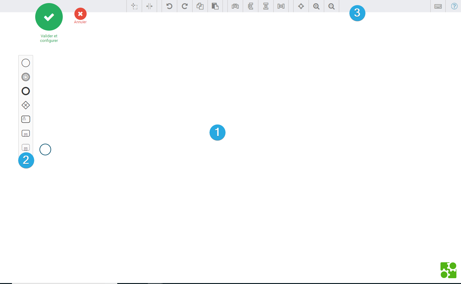
1️⃣ The drawing area: this is where you can draw the process as you wish to model it.
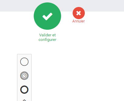
2️⃣ BPMN elements: these are the BPMN elements that you can drag and drop into the drawing area. You can find the different BPMN items in this menu:
See the BPMN elements fact sheet
3️⃣ The action bar: it allows you to save your model, to delete, copy, paste, cut elements…
Save changes
To save the current state of the process and switch to its configuration, simply click on the button to: Validate and configure.
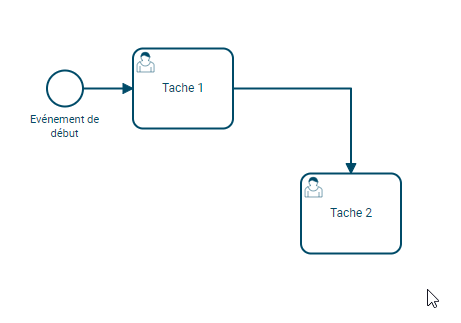
Add the first elements and link them together
The Departure Event
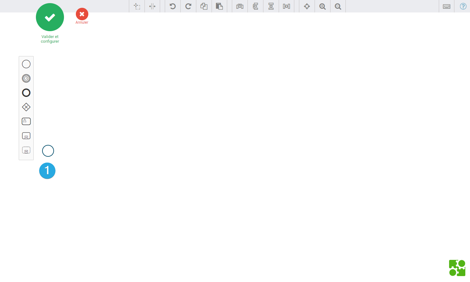
To add elements to the drawing area, simply drag and drop one of the elements from the left menu to the drawing area.
Iterop automatically places the start event 1️⃣ (start event) in the drawing area. Therefore, there is no need to add one.
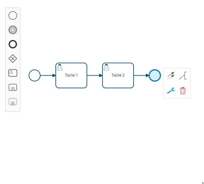
Add an activity related to the start event
- Click on the start event. Icons representing BPMN items are displayed to the right of the selected item.
- Click and hold the 1st icon to add a “Human Task” type activity and drag and drop the activity next to the event.
- A human task is now added and linked to the starting event.

Linking two activities together
- Use the menu to add a “Human Task” activity.
- Click on the item preceding the new activity to be linked
- Click on the arrow
- Drag and drop the item on the task created in this way.
- The two tasks are thus linked together by an arrow (also called sequence flow).
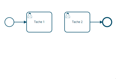
It would have been possible to add a new human task by proceeding in the same way as after the initial event.
Other items to be added
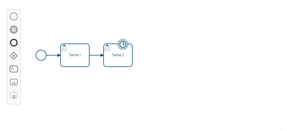
Adding a border event on an activity
To add a border event related to an activity :
- In the menu on the left, choose “Intermediate Catch Event”.
- Place the item on one of the sides of the chosen activity. Borders are colored orange to indicate that it is possible to drop a border event.
- If necessary, click on the wrench to change the type: edge signal, edge timer, edge signal
- Continue the modeling as seen previously by clicking on the element in question to choose a new element.
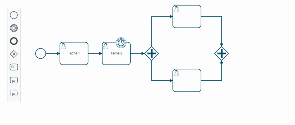
Create a logical door to open parallel branches
To create a logical gate of type AND :
- Select the task upstream of the logical gate and click on the diamond.
- The default logic gate that is created is an XOR logic gate. We have to turn it into an AND door.
- Select the logical door and then click on the wrench at the bottom left.
- A menu will open allowing you to change the type of the logic gate.
- Select Parallel gate (AND)
- Continue your process by adding elements from the logic gate. Once the elements have been added, this logical door must be closed. Click on one of the activities preceding the end of the logic gate
- Click on the diamond
- Proceed as in steps 1, 2 and 3 to add and modify it to logical AND gate.
- Connect all activities in the parallel branches to the final logic gate using the arrows.
It is then possible to add elements after the closing AND logic gate.
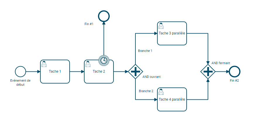
End the process by adding an end event
For a process to be valid, all elements must lead to an end event.
As shown in the previous example, the logical AND gate must be linked to an end event :
- Select the last logical gate and click on the end event.
- Drag and drop the end element to the right of the logic gate.
Modify existing elements
Rename an item
To give a name to an element :
- Double-click on the element to rename
- A text field will appear on the task
- Enter the new item name.
- Click anywhere else, the element takes the name you entered.
It is possible to name any element of the process by double-clicking on it. Here is an example where all the elements are named :
Change sequence flows (arrows between two elements)
It is possible to modify the sequence flows, in order to make the diagram of the final process more aesthetically pleasing. This will not affect the execution, only the diagram image.
- Click on the sequence flow you want to change
- A new yellow dot will appear on the sequence stream. It is possible to move this new stitch to create an “elbow”. You can add as many elbows as you like.

